偏置滑塊機構是滑塊之滑動方向與水平方向有ㄧ距離e,此稱偏置量,而偏置量會影響滑塊的移動範圍。若曲柄角度限制於某ㄧ範圍,連桿長度應該不會造成問題。但是如果曲柄要完成360度的旋轉,則連桿之間得長度須依其所能夠成之三角形關係而定。聯結桿長必須要比曲柄長。若有偏置情形時,則聯結趕與曲柄長度差應大於偏置距離e,當垂直狀態是最小距離。
當聯結趕和曲桿的差大於偏至距離e才會有兩個界限角,而界限角是當曲柄和聯結桿都在一直線上時,曲柄的水平角度。以滑塊為主動的時候,當曲柄轉到界限角的時候(連趕和曲桿重疊時候)滑塊就不能再往後運動,到達界限角之後,滑塊又往前運動。而曲柄到另一界限角角的時候(聯結桿和曲桿成ㄧ直線有最大距離),不能再往前運動而就往後運動。
當聯結趕和曲桿的差大於偏至距離e才會有兩個界限角,而界限角是當曲柄和聯結桿都在一直線上時,曲柄的水平角度。以滑塊為主動的時候,當曲柄轉到界限角的時候(連趕和曲桿重疊時候)滑塊就不能再往後運動,到達界限角之後,滑塊又往前運動。而曲柄到另一界限角角的時候(聯結桿和曲桿成ㄧ直線有最大距離),不能再往前運動而就往後運動。
當聯結趕和曲桿差小於篇至距離e,而就只有ㄧ界限角聯結趕和曲桿成ㄧ直線有最長距離時),而另一個界限角式不純在。因為當這種條件下曲桿不能選轉一圈,而最大旋轉範圍是當聯結桿與偏至距離e的方向上平行時(聯結桿垂直於水平面)。
而已知條件下R=10+(07) L=R+5=23 e=10 L-R<e 為第二種情況,因此上述分析而能做成動畫。
function [s,theta21,theta22]=slider_limit(R,L,e)
% P4.7   [s,th1,th2]=slider_limit(r)
%
% Find the stroke, extreme angles of link 2 in a slider mechanism system
% Input:R,L lengths of crank & connecting rod; e the offset of block
% Output: s:stroke, theta21:angle for the right position,
%         theta22:angle for the left position
% Examples:
%    [s,th1,th2]=slider_limit(5,12,3)
%
% Designed by D.S. Fon, BIME, NTU, Date:October 17,2002.
d2g=pi/180;
th1=asin(e./(R+L));
th2=asin(e./abs(R-L));
s=(R+L).*cos(th1)-abs(R-L).*cos(th2);
theta21=th1/d2g;
theta22=th2/d2g;
function [d,theta3]=slider_solve(theta2,R,L,e,mode)
% P4.8 [d,theta3]=slider_solve(theta2,R,L,e)
%
% Find the block coordinate and angle of connecting rod in a slider-crank system
% Input:R,L lengths of crank & connecting rod; e the offset of block
% theta2: angles of crank, cane be a matrix
% Output: d:distance of the block from the origin.
% theta3:angle of the connecting rod,
% Examples:
% [d,theta3]=slider_solve(45,5,10,3)
%
% Designed by D.S. Fon, BIME, NTU, Date:Fegruary 9,2003.
if nargin<5, mode="0;end" d2g="pi/180;" theta="theta2*d2g;" cc="(e-R.*sin(theta))./L;">=0,
theta3=asin(cc);
else
theta3=asin(-cc)+pi;
end
d=L.*cos(theta3)+R.*cos(theta);
theta3=theta3./d2g;上面程式為機動學光碟裡程式,運用上面程式再配合下面所寫程式即可畫出連桿
function slider_draw1(R,L,e)
%R為曲桿 L為聯結桿 e為偏至距離
%example:slider_draw1(17,23,10)
[s,theta21,theta22]=slider_limit(R,L,e)
thea2=asind((L-e)/R)+180;
ang=linspace(theta21,thea2,100);%分成100個點
[d,theta3]=slider_solve(ang,R,L,e,1)
x=R*cosd(ang);
y=R*sind(ang);
for n=1:100
link_plot([0,x(n),d(n)],[0,y(n),e],2);%此為之前程式
line([d(n)-3,d(n)+3,d(n)+3,d(n)-3,d(n)-3],[e-2,e-2,e+2,e+2,e-2]);%畫出滑塊
axis equal
axis ([-45 45 -30 30]);
pause(0.01)
clf
end
thea3=asind((L-e)/R);
ang=linspace(thea2,-thea3,100);
[d,theta3]=slider_solve(ang,R,L,e,-1)
x=R*cosd(ang);
y=R*sind(ang);
for n=1:100
link_plot([0,x(n),d(n)],[0,y(n),e],2);
line([d(n)-3,d(n)+3,d(n)+3,d(n)-3,d(n)-3],[e-2,e-2,e+2,e+2,e-2]);
axis equal
axis ([-45 45 -30 30]);
pause(0.01);
clf
end
thea3=asind((L-e)/R);
ang=linspace(-thea3,theta21,100);
[d,theta3]=slider_solve(ang,R,L,e,1)
x=R*cosd(ang);
y=R*sind(ang);
for n=1:100
link_plot([0,x(n),d(n)],[0,y(n),e],2);
line([d(n)-3,d(n)+3,d(n)+3,d(n)-3,d(n)-3],[e-2,e-2,e+2,e+2,e-2]);
axis equal
axis ([-45 45 -30 30]);
pause(0.01);
clf
end
上述程式所做動畫如下(滑塊為主動)
若以老師講義的函式分析,當在使用sld_angle_limits時其中缺少了r3≧r4≧0,r3+r4≧r2,因此只要把
elseif r3+r4>=r2 & r3>=r4 & r4>=0,
Qstart=-asin((r3-r4)/r2);
Qstop=pi+asin((r3-r4)/r2);
就能跑出正確答案。
曲桿為主動
>> drawsldlimits([10,17,23,10],0,1,0)
Qstart =
-49.8808
Qstop =
229.8808
滑塊為主動
>> drawsldlimits([10,17,23,10],0,1,2)
Qstart =
-38.7298
Qstop =
38.7298
 使用講義上的函式drawsldpaths(r6,th6,r,th1,td2,tdd2,sigma,npts,driver,mode)即可畫出連續圖形
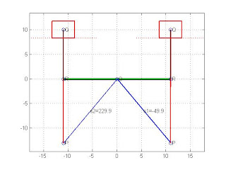
第二連桿為主動(閉合型)
Qstart =
-49.8808
Qstop =
229.8808

第二連桿為主動(分支型)
>> drawsldpaths(0,0,[10,17,23,10],0,10,0,-1,100,0,0)
Qstart =
-49.8808
Qstop =
229.8808
閉合型和分支型的連續圖形極限位置角度相同,但是從上面兩圖中可看出圖形上有對偁。
滑塊為驅動桿(閉合型)
>> drawsldpaths(0,0,[10,17,23,10],0,10,0,1,100,2,0)
Qstart =
-38.7298
Qstop =
38.7298
滑塊為驅動桿(分支型)
>> drawsldpaths(0,0,[10,17,23,10],0,10,0,-1,100,2,0)
Qstart =
-38.7298
Qstop =
38.7298
 講義上函式無法以滑塊為主做成動畫,因此只能畫出以曲桿為主動的動畫
曲桿為主動(閉合型)
曲桿為主動(分支型)


1 則留言:
做得相當好,分析內容很充實
張貼留言